
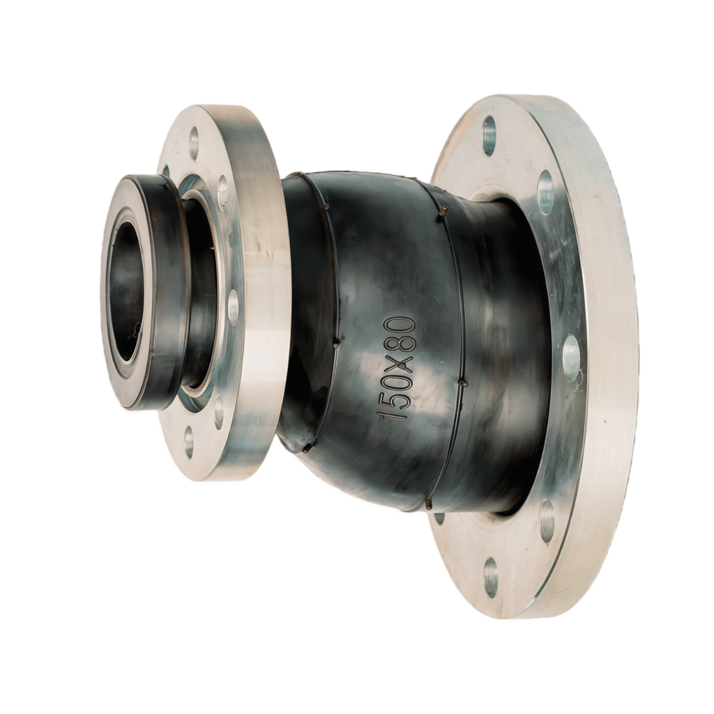
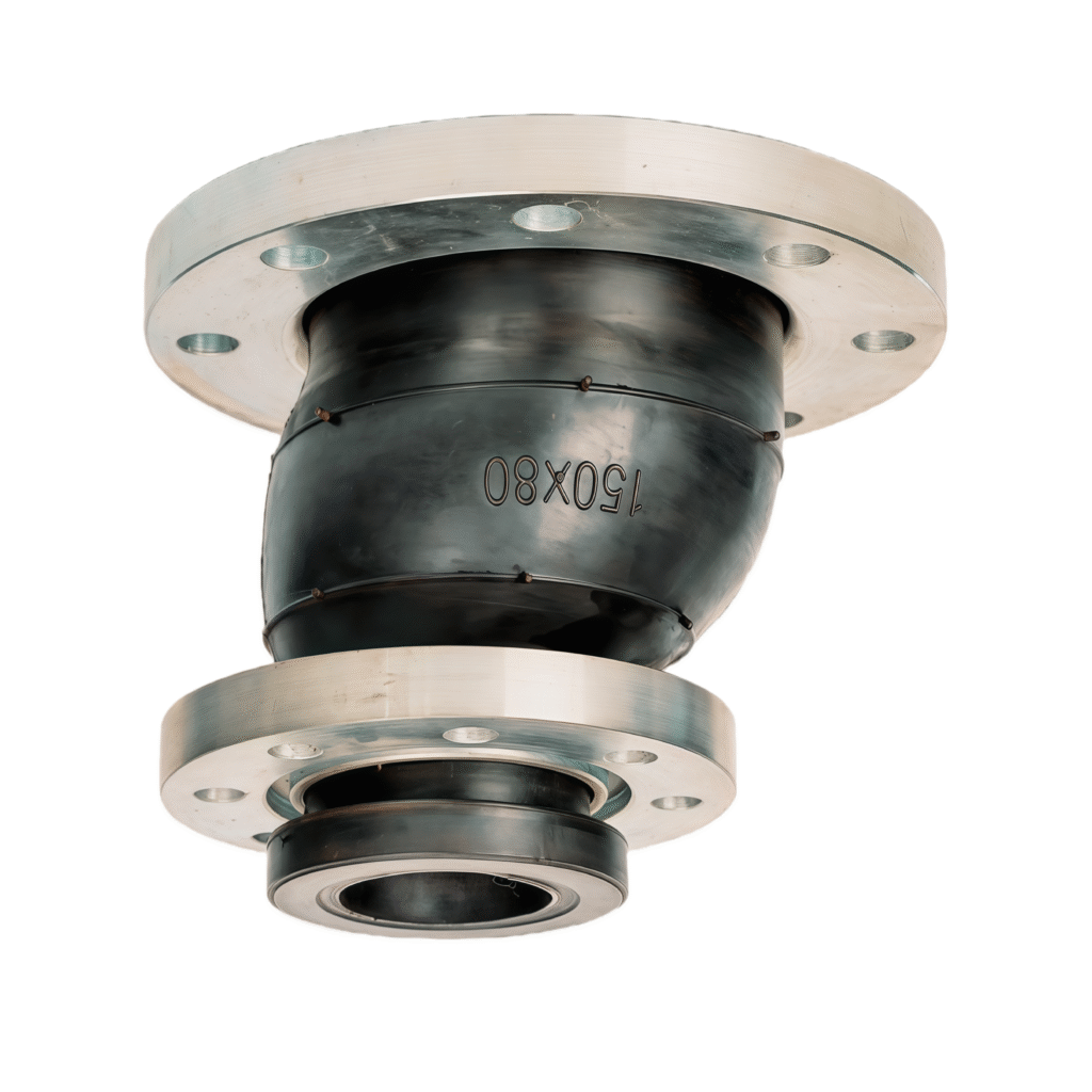
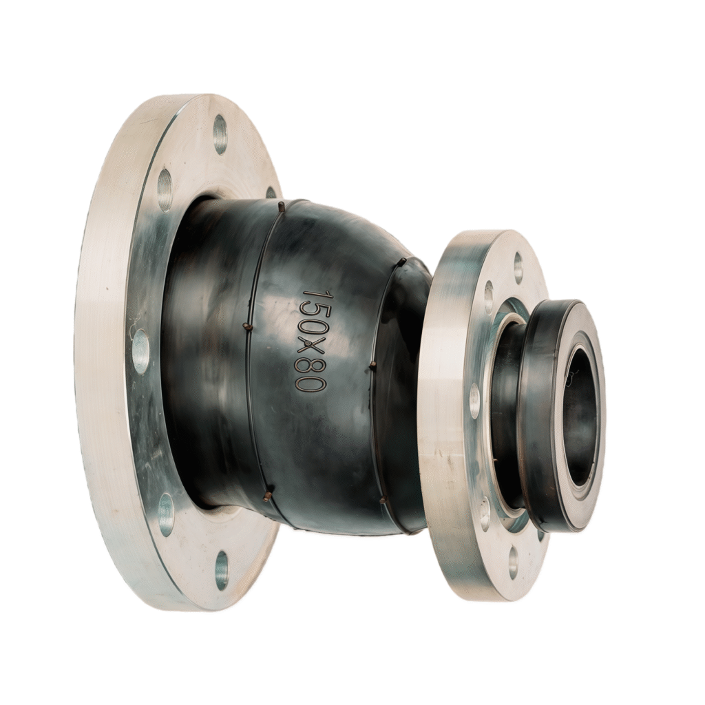
Eccentric reducing rubber joint
| size | DN25 to DN500 |
| pressure | PN6~PN25 |
| temperature | -15 ~ 80℃ |
| Flange Standard | DIN, ANSI, JIS etc |
| Flange material | Stainless Steel 304, 316, 321 etc |
| rubber material | EPDM, natural rubber, NBR rubber and neoprene rubber |
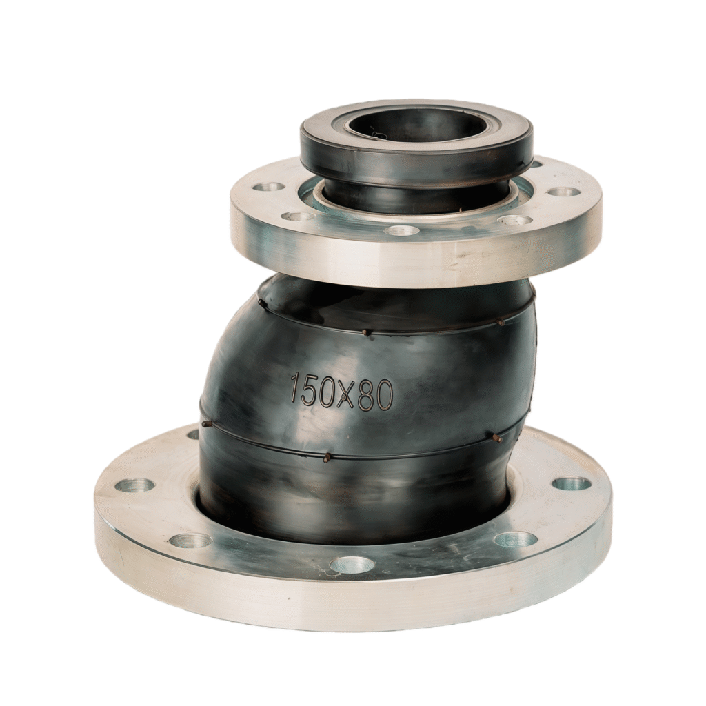


Overview
Reducing flexible rubber joint is widely used in the field of chemical industry, construction, supply water, sewage drainage, petroleum, light and heavy industry, sanitation, plumbing, electricity and other fundamental engineering.
The inner seamless high-pressure rubber joint is developed by us which prevents corrosive medium from etching the inner wall of the rubber joint in high temperature, acid, alkali and oil resistance pipeline, whereby it also can extend its service life span. Structural noise transmission can be reduced with the restrictive and flange non-parallelism.
Reducing flexible rubber joint is composed of fabric reinforced and metal flange loose joint.
It has the characteristics of compact structure, light weight, high flexibility, easy installation, long service life.
| Nominal Diameter (mm) | LengthL (mm) | Axial displacement (mm) | Haorizontal isplacement (mm) | Angular deflection(a1+a2)° | |
|---|---|---|---|---|---|
| Extension | Compression | ||||
| 40×25 | 115 | 7 | 12 | 10 | 10 |
| 40×32 | 125 | 7 | 12 | 10 | 10 |
| 50×40 | 180 | 7 | 12 | 10 | 10 |
| 65×40 | 180 | 7 | 12 | 10 | 10 |
| 65×50 | 180 | 7 | 12 | 10 | 10 |
| 80×50 | 180 | 7 | 12 | 10 | 10 |
| 80×65 | 180 | 7 | 12 | 10 | 10 |
| 100×50 | 180 | 7 | 12 | 10 | 10 |
| 100×65 | 180 | 7 | 12 | 10 | 10 |
| 100×80 | 180 | 8 | 14 | 12 | 10 |
| 125×65 | 200 | 8 | 14 | 12 | 10 |
| 125×80 | 200 | 8 | 14 | 12 | 10 |
| 125×100 | 200 | 10 | 20 | 12 | 10 |
| 150×50 | 200 | 10 | 20 | 12 | 10 |
| 150×65 | 200 | 10 | 20 | 12 | 10 |
| 150×80 | 200 | 10 | 20 | 12 | 10 |
| 150×100 | 200 | 10 | 20 | 12 | 10 |
| 150×125 | 200 | 12 | 20 | 14 | 10 |
| 200×80 | 200 | 12 | 20 | 14 | 10 |
| 200×100 | 200 | 12 | 20 | 14 | 10 |
| 200×125 | 200 | 12 | 20 | 14 | 10 |
| 200×150 | 200 | 12 | 20 | 14 | 10 |
| 250×125 | 220 | 12 | 20 | 14 | 10 |
| 250×150 | 220 | 12 | 20 | 14 | 10 |
| 250×200 | 220 | 12 | 20 | 20 | 10 |
| 300×125 | 220 | 14 | 22 | 20 | 10 |
| 300×150 | 220 | 14 | 22 | 20 | 10 |
| 300×200 | 220 | 14 | 22 | 20 | 10 |
| 300×250 | 220 | 14 | 22 | 20 | 10 |
| 350×150 | 240 | 14 | 22 | 20 | 10 |
| 350×200 | 240 | 14 | 22 | 20 | 10 |
| 350×250 | 240 | 14 | 22 | 20 | 10 |
| 350×300 | 240 | 14 | 22 | 20 | 10 |
| 400×200 | 240 | 14 | 22 | 20 | 10 |
| 400×250 | 240 | 14 | 22 | 20 | 10 |
| 400×300 | 240 | 14 | 22 | 20 | 10 |
| 400×350 | 240 | 14 | 22 | 20 | 10 |
| 450×300 | 240 | 14 | 22 | 20 | 10 |
| 450×350 | 240 | 14 | 22 | 20 | 10 |
| 450×400 | 240 | 14 | 22 | 20 | 10 |
| 500×350 | 240 | 14 | 22 | 20 | 10 |
| 500×400 | 240 | 14 | 22 | 20 | 10 |
| 500×450 | 240 | 14 | 22 | 20 | 10 |
| Note: 1. Special requirements can be made according to user drawings. The sphere can be made of nitrile rubber, EPDM, chloroprene rubber and other materials. 2. For suspended water supply, use products above DN200. The pipeline must have a fixed support or fixed bracket, otherwise the product should be installed with an anti-pull-off device. 3. If the user uses a rubber joint, the corresponding flange should be a valve flange. | |||||
